Turnstiles
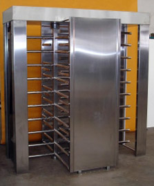
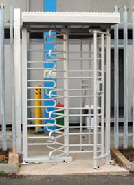
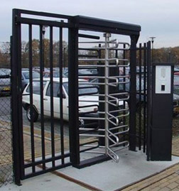
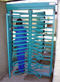
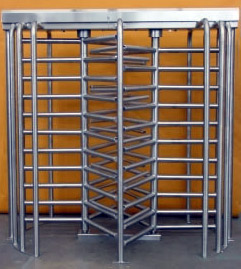
Full Height Industrial Turnstiles
 |
 |
|---|---|
 |
 |
 |
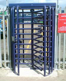 |
Designed for maximum impenetrability to automatically guide personnel in and out of secure areas.
Turnstile Operation
Type ELO: Exit or entry rotation is allowed by signal from Card Reader, Biometric Reader, Remote Control, Push-button, Control panel, etc. Turnstile is fitted with STD 100 locking arrangement.
Type MO: Rotation in either both directions or one predetermined direction freely on hand-push. Turnstile is fitted with WUNL arrangement, and is not lockable as standard but has lockable option.
Rotation in either both directions or one predetermined direction freely on hand-push. Turnstile is fitted with WUNL arrangement, and is not lockable as standard but has lockable option.
Type BIO: Exit or entry rotation is allowed by signal from a single Biometric/Fingerprint Reader situated in the middle of the Turnstile thus eliminating the need for two readers.
Turnstile Lock Mechanism
The bi-directional, shock absorbent turnstile lock mechanism (STD 100) is of a simple robust design whereby lock and release arrangement is operated by linear motors. Emergency release mechanical override (fitted with a security lock to avoid misuse) is provided for free gate rotation or positive lock when desired, in case of electrical power or control system failure. A spring-loaded device prevents the gate from further rotation after the user stops pushing on the gate arm and positions the rotor into its "locked position".
Automatic control prevents the gate from turning in the forbidden direction once rotor has moved through 45º from rest.
An "automatic lock-up" locking arrangement is a standard turnstile feature. Should the mains power fail or be switched off, the turnstile becomes locked in both directions. It can then be unlocked in the desired direction mechanically with a key. An "automatic unlock" locking arrangement is offered as an option.
Design Features
Main Frame: Sturdy, fully welded construction manufactured from low carbon steel heavy channels, flats and square hollow sections. The hollow sections provide ideal conducting power and control cables.
Four Arm Rotating Gate: Square hollow centre column with end shafts located in sealed bearing blocks with welded on 32 diameter tube gate arms curved to U-shaped loops.
Barrier in forbidden Direction: 38 diameter tubing fitted with protective end cups on double turnstile; 32 diameter tubing curved to U-shaped loop on single turnstile.
Installation
All units are completely factory assembled and tested, minimizing installation time.
BUILDING REQUIREMENTS
Firm levelled concrete screed plinth with a minimum strength of 20Mpa, suitable to accept drill-in M12 x 75mm long anchor bolts.
Model HTG: Plinth 1600 x 1000; 8-off M12 Anchor Bolts drilled in on installation.
Model DHTG: Plinth 2400 x 1000; 12-off M12 Anchor Bolts drilled in on installation.
Electrical Power Requirements
220V single phase 50Hz; power consumption: 2,3 amps at 24 volts Dc per lock arrangement.3 core (220V AC, 15A) power cable. (7 core x 0,5mm min cable if push-button control is required) on turnstile rotor centreline - on top - for connecting into lock arrangement and Standard Control Logic respectively. Standard Control Logic is offered to interface turnstile lock arrangement with controls supplied by others (card-reader, push-button, tokens, etc.).
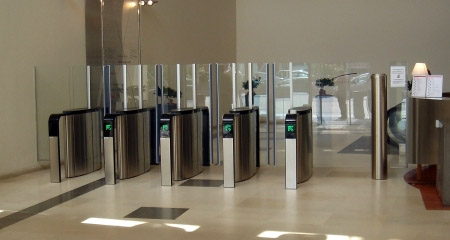
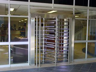
PRESTIGE TURNSTILES
Full height and waist height prestige high quality turnstiles designed for the corporate customer to guide personnel in security areas.
 |
|---|
 |
 |
 |
Operation
TURNSTILE LOCK STD 100: From a locked position, the turnstile's exit or entry rotation can be facilitated by a variety of methods, including: electronic controls, electric remote control magnetic ID card and push-button control. An automatic "fail-secure" lock-up locking arrangement is a standard feature. Should the mains power fail or be switched off, the gate becomes locked in both directions and can then be unlocked in the desired direction mechanically with a key. Optional "fail-safe" locking arrangement is available on request.
Lock Mechanism
The bi-directional, shock absorbent turnstile lock mechanism is of a simple yet robust design. The lock and release arrangement is operated by liner motors and limit switches. A hydraulic damping device provides a cushioned homing feature whilst returning the rotor arm to its neutral horizontal no-entry position.
Design Features
TURNSTILE ROTORS: 180 grid finish stainless steel 38 diameter tubing is fitted into solid diameter chromed plated and polished rotor hub. TURNSTILE PEDESTALS: The low-carbon and stainless steel plate pedestals are suitably designed. Top covers are housing the locking mechanism and control logic. Stainless steel top cover is hinged and lockable to facilitate easy yet secure maintenance access to provide ergonomically and aesthetically pleasing appearance.
Main Frame: Sturdy, fully welded construction manufactured from low carbon steel heavy channels, flats and square hollow sections. The hollow sections provide ideal conducting power and control cables.
Four Arm Rotating Gate: Square hollow centre column with end shafts located in sealed bearing blocks with welded on 32 diameter tube gate arms curved to U-shaped loops.
Barrier in forbidden Direction: 38 diameter tubing fitted with protective end cups on double turnstile; 32 diameter tubing curved to U-shaped loop on single turnstile.
Aesthetics
Our Turnstiles' pedestals and rotors combine cost-effectiveness and aesthetic appearance. Even the basic low-security model with stainless steel or baked enamel finish are at home with their surroundings while remaining aptly functional. The construction and option of the more sophisticated equipment allows for a complete tone-in with any architectural design.
Our STD Turnstile Logic panel is offered to interface turnstile locking arrangement with controls supplied by other contractors (card-reader, push-button, tokens, etc.). It comprises an 80VA transformer with rectifier converting 220V AC to power lock arrangement and control boards.
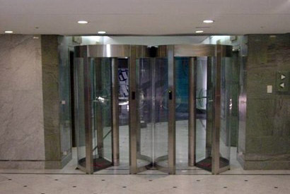
MANUAL, AUTOMATIC & ACCESS CONTROL REVOLVING DOORS
Automatic Revolving Doors
 |
|---|
 |
 |
 |
Operation Options
The operation of the automatic revolving door is facilitated by Card Readers and/or a Control Station with a selection of 4 modes of operation - Controlled Access, Free Access, Emergency and Night Lock mode.
Controlled Access Entry/Exit Mode
a) From a locked position, the revolving door is unlocked by a remote signal via IN or OUT push-buttons, or by a card reader positioned on the door. It may only rotate in the direction instigated by a hand-push.
b) If the door is pushed in the chosen direction through approximately 3 degrees (after release signal IN or OUT has been received) the door will be driven through 90 degrees of movement and will then lock.
Free Access Entry/Exit Mode
a) When the user activates the door by pushing in the chosen direction by approximately 3 degrees, the door will automatically start revolving through 360 degrees of movement before coming to rest.
b) If another person enters the revolving door during the "coming to rest" period the door is re-energized for a further 360 degree movement.
c) The door may be locked at any time during the free access mode. However, several degrees of rotation must be allowed for, as movement of the revolving door must be slowed down prior to locking.
Emergency Mode
The door is unlocked and the rotor freely revolves in both directions.
Night Lock Mode
It locates rotor in 45 degree position and locks - i.e. it provides maximum "double leaf" securityOur STD Turnstile Logic panel is offered to interface turnstile locking arrangement with controls supplied by other contractors (card-reader, push-button, tokens, etc.). It comprises an 80VA transformer with rectifier converting 220V AC to power lock arrangement and control boards.
Door User Safety
If the user moves slowly or accidentally stops, the door will sense and obstruction and stop, exerting only a negligible force. In addition, an optional safety switch on each upright of the outer casing is available.
Manual Mode
The door rotor operation is manual and it is "locked" mechanically. A standard feature is the self-centring function that stops the rotor in a "locked" position.
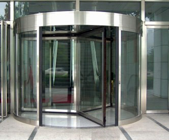
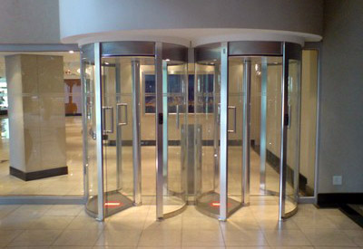
Design Features
Flow Systems offers Revolving Doors from 1.4 meters in diameter to 5 meters. The main frame of the Revolving Doors is of sturdy fully welded construction, structurally self-contained, from low-carbon steel heavy channels, flat bars and square hollow section combined with aluminum, or stainless steel, or baked enamel painted steel on all visible surfaces. All unexposed metal parts are painted for corrosion protection. The four leaf revolving rotor either of reinforced aluminum "space frame" glazed with 8.5mm thick laminated clear glass, or frame less with 12mm thick toughened glass.
Aesthetics
All revolving doors have a finish of the highest quality. The lasting impression is of an attractive entrance created by a combination of clean vertical and horizontal lines and the cylinder of the door. The rotor appears light, but is of a strong "space frame" design. The floor is covered by optional rugged carpet, or by the tiles of the entrance. The outer body is available with solid curved glass side panels, or with steel, stainless steel or aluminum panels for highest quality finish.
Installation
Revolving Doors are all completely factory assembled and tested to minimize installation time. The area floor surface mounting requires the floor to have a leveled surface with a minimum strength of 25Mpa, suitable to accept M10 x 100mm anchor bolts. The unit mass is approximately 500Kg's and its electrical power requirement is 880 V AC 3A (depending on Revolving Door model chosen).
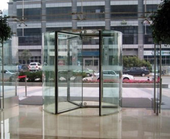
New Revolving Door Design
2 Wing Revolving Door as opposed to the standard 3 and 4 wing doors is now also available - This door can be used as an Automatic Sliding Door as well, if and when necessary or as an Emergency Exit or to move large objects through the door, for example cars, etc. as opposed to the standard 3 and 4 wing doors is now also available - This door can be used as an Automatic Sliding Door as well, if and when necessary or as an Emergency Exit or to move large objects through the door, for example cars, etc. as opposed to the standard 3 and 4 wing doors is now also available - This door can be used as an Automatic Sliding Door as well, if and when necessary or as an Emergency Exit or to move large objects through the dor, for example cars, etc as opposed to the standard 3 and 4 wing doors is now also available - This door can be used as an Automatic Sliding Door as well, if and when necessary or as an Emergency Exit or to move large objects through the dor, for example cars, etc.
ACCESS CONTROL BOOTHS, CUBICLES, MANTRAPS
Designed for maximum impenetrability to automatically guide personnel in security areas
Many different models available for mines, banks, offices, etc.
Modes
MOD - Semi-automatic, Mechanical
EOD - Automatic, Electrical
.jpg) |
.jpg) |
|---|---|
.jpg) |
.jpg) |
Operation
Model MOD has mechanically operated doors which, from a locked position, unlock by means of a signal from an electrical remote control, card reader, etc. The door is opened manually and closed automatically by means of a "non hold open" door closing arrangement with adjustable closing speed. The doors are fitted with push/pull handles and are locked with two electro-magnetic locks. Model EOD has similar features, except that door opening, closing and locking is automatically controlled by electrical operators.
The open/close interval is approximately 4 seconds in the case of models EOD (i.e. 8 seconds in total). In the case of the MOD model, the operating time depends largely on the user. Model MOD will, and EOD can, unlock both doors in the case of electrical power failure. Interior sensing devices monitor the user's presence. Standard Flow Systems logic is supplied to interface with cubicle operating components. Controls, Card reader, etc. are be supplied by other contractors.
Installation
All units are dispatched completely assembled and factory tested, minimizing installation time. Units may be floor surface mounted. A leveled surface with a minimum strength of 25Mpa is required, suitable to accept 4 off m10 x 50mm H.D. anchor bolts. The cubicle mass is approximately 300kg, and its electrical requirements are 220VAC 15A 50Hz.
Design
The Cubicle Model 541 door locks are concealed to eliminate tampering. Units are of fully welded low carbon steel construction with polished stainless steel and silver vein baked powder coat finishes. Frameless doors are of clear 12mm armor plate glass with top and bottom rails
Options Available
* Glass side panels
* Stainless Steel and Aluminum cladding
* Various colours of baked powder coating
* Steel framed doors fitted with laminated glass or other materials
* Push/Pull door handles (cubicle type EOD & MOD)
![]()